In this course, we will teach you the newest Python programming for robots.
This is the first Python and HTML specific course for robotics anywhere. Learn how to make your own robots, and how to control them from your Smartphone using easy HTML websites.
MicroPython is a brilliant adaption of Python for embedded IoT that is a revolution in software. It combines simplicity with power and fits in just 1MB of memory! There's nothing else like it. Let's get started.
Check out your HEXLINK.
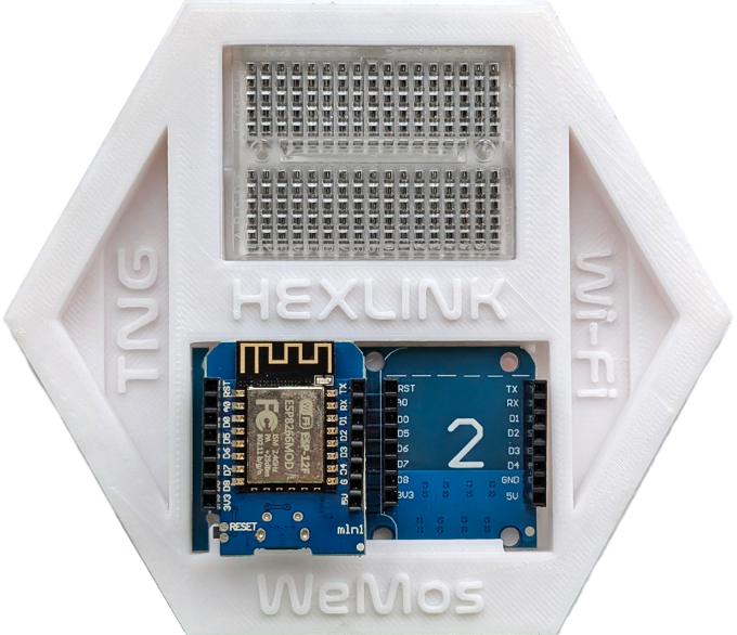
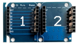
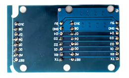
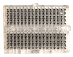
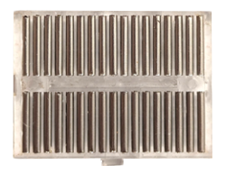
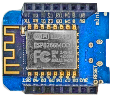
This includes a WeMos, Dual Base, and Breardboard. What's in your HEXLINK?
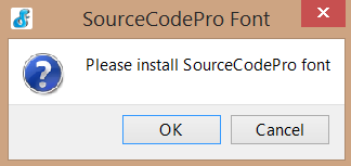
2. Download the Software:
 Alert 2
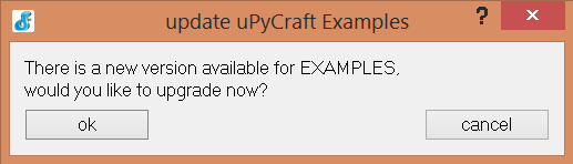
Learn how to turn an LED on/off using Digital Pins. These work like binary signals, either HIGH (on) or LOW (off), representing discrete voltages.
LOW: 0 Volts (Digital Pin near 0V, or off)
HIGH: 3.3 Volts (Digital Pin near 3.3V, or on).
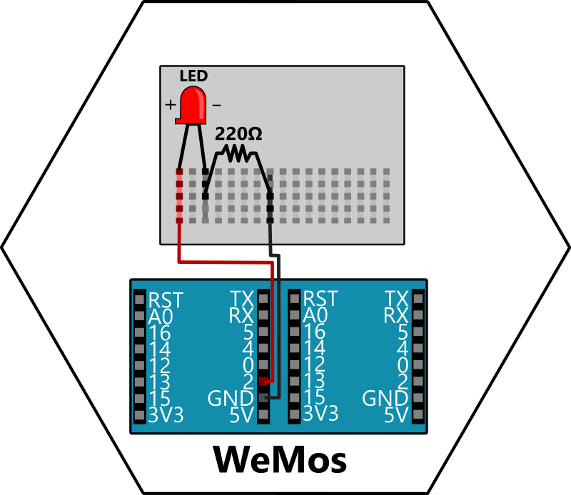
1. Start by wiring your first LED circuit.
2. In uPyCraft, open a new file  and add this code.
from machine import Pin
from time import sleep

led = Pin(2, Pin.OUT)

while True:
  led.value(not led.value())
  sleep(1)
from machine import Pin
from time import sleep
led = Pin(2, Pin.OUT)
while True:
  led.value(not led.value())
  sleep(1)
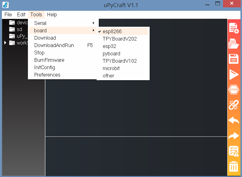
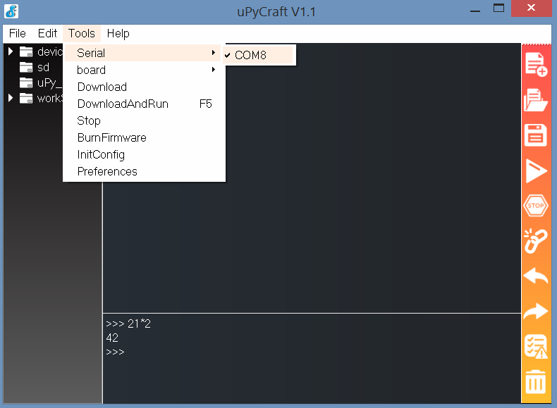
Before Upload  (1) Save your code. (2) Set board to esp8266. (3) Set usb Serial port.
FAQs
Sense light with a Photoresistor using Analog Pins. Your WeMos has an ADC (Analog-to-Digital Converter) on Analog Pin (A0) that reads values between the range of 0 to 1023, corresponding to 0V to 3.3V. We'll also learn a new feature of our Dual Base, by wiring our next connection on its right side (2).

1. Diagram for wiring your ADC circuit.
2. In uPyCraft, open a new file and add this code.
from machine import ADC
from time import sleep

photoresistor = ADC(0)

while True:
    light = photoresistor.read()
    print("Light Level:", light)
    sleep(0.5)
from machine import Pin
from time import sleep
photoresistor = ADC(0)
while True:
    light = photoresistor.read()
    print("Light Level:", light)
    sleep(0.5)
Before Upload (1) Save your code. (2) Set board to esp8266. (3) Set usb Serial port.
Create a mini Nightlight that turns on/off based on the light level in your environment.
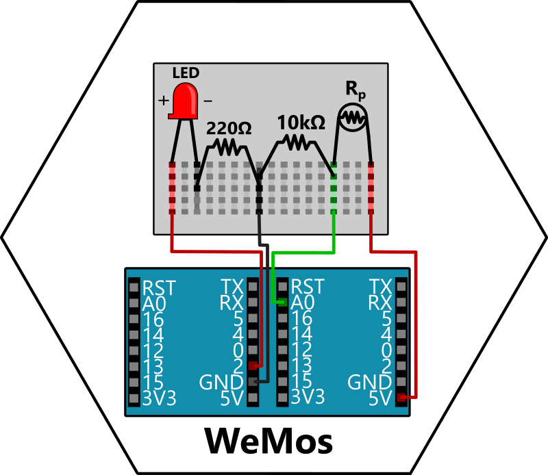
1. Diagram for wiring your Nightlight circuit.
2. In uPyCraft, open a new file and add this code.
from machine import ADC, Pin
from time import sleep

photoresistor = ADC(0)
led = Pin(2, Pin.OUT)
LIMIT = 300

while True:
    light = photoresistor.read()

    if light  < LIMIT:
        led.on()
    else:
        led.off()

    print("Light Level:", light)
    sleep(0.2)
from machine import Pin
from time import sleep
photoresistor = ADC(0)
led = Pin(2, Pin.OUT)
LIMIT = 300
while True:
    light = photoresistor.read()

    if light < LIMIT:
        led.on()
    else:
        led.off()

    print("Light Level:", light)
    sleep(0.2)
Before Upload (1) Save your code. (2) Set board to esp8266. (3) Set usb Serial port.
This code creates an IoT application to control an LED over Wi-Fi.
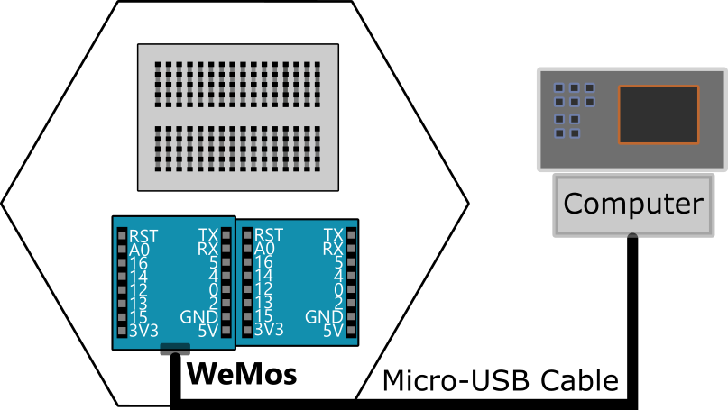
The WeMos operates on 2.4 GHz Wi-Fi networks. It does not support 5 GHz Wi-Fi networks. Thankfully, most Smartphones can setup a 2.4 GHz Wi-Fi Hotspot these days, which works as long as you connect your WeMos and Smartphone to the same Hotspot.
1. WeMos connects to a 2.4 GHz Wi-Fi network.
2. WeMos turns into a web server host on port 80.
3. When a web browser (that must be on the same Wi-Fi network) goes to the IP address, then the WeMos returns a HTML website. You can then toggle the LED simply by visiting a website.
4. Clicking a button on this website sends a request (/on or /off) to the server.
5. The server reads the request, toggles the LED, and updates the web browser.
Update the Wi-Fi setup code with your Wi-Fi details before uploading to the WeMos.
from machine import Pin
import network
import socket

# LED setup
led = Pin(2, Pin.OUT)

# Wi-Fi setup
ssid = 'Your-WIFI'
password = 'Your-PASSWORD'
wlan = network.WLAN(network.STA_IF)
wlan.active(True)
wlan.connect(ssid, password)
while not wlan.isconnected():
    pass
print('Wi-Fi connected, see website at:', wlan.ifconfig()[0])

# HTML website code
html = """
<!DOCTYPE html>
<html>
<body style='text-align:center;'>
    <h1>Toggle LED</h1>
    <form action='/on'><button>Turn ON</button></form>
    <form action='/off'><button>Turn OFF</button></form>
</body>
</html>
"""

# Start web server
server = socket.socket()
server.bind(('', 80))
server.listen(1)
print('Server running...')

# Handle web requests
while True:
    conn, _ = server.accept()
    request = conn.recv(1024).decode()
    led.on() if '/on' in request else led.off() if '/off' in request else None
    conn.send("HTTP/1.1 200 OK\r\nContent-Type: text/html\r\n\r\n" + html)
    conn.close()
from machine import Pin
import network
import socket
# LED setup
led = Pin(2, Pin.OUT)
# Wi-Fi setup
ssid = 'Your-WIFI'
password = 'Your-PASSWORD'
wlan = network.WLAN(network.STA_IF)
wlan.active(True)
wlan.connect(ssid, password)
while not wlan.isconnected():
    pass
print('Wi-Fi connected, see website at:', wlan.ifconfig()[0])
# HTML website code
html = """
<!DOCTYPE html>
<html>
<body style='text-align:center;'>
    <h1>Toggle LED</h1>
    <form action='/on'><button>Turn ON</button></form>
    <form action='/off'><button>Turn OFF</button></form>
</body>
</html>
"""
# Start web server
server = socket.socket()
server.bind(('', 80))
server.listen(1)
print('Server running...')
# Handle web requests
while True:
    conn, _ = server.accept()
    request = conn.recv(1024).decode()
    led.on() if '/on' in request else led.off() if '/off' in request else None
    conn.send("HTTP/1.1 200 OK\r\nContent-Type: text/html\r\n\r\n" + html)
    conn.close()
Before Upload (1) Save your code. (2) Set board to esp8266. (3) Set usb Serial port.
Hey!
We think you are pretty cool.
Interests
Robots Fun Education Games Friends Events 3D Prints Code Design Art workshops
 Visit Our YouTube Channel